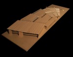
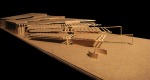
Unfortunately my diagrams did not help me to determine spatial relationships. However, they were useful in determining my overall goal for the project, which was to use the trusses from the Wheatly School to sort of grab the incoming greenway users and pull them into the program and transit station, as well as push the transit users out towards the program and greenway, unifying not only the composition, but the types of people illustrated my diagrams. Another concept shown in the model is the thought of having the pieces of program “step down” from I-110.
May 20, 2010
Transit Station
Posted by codymblanchard under Cody Blanchard, Uncategorized | Tags: Cody Blanchard |Leave a Comment
May 8, 2010
Transit Diagrams
Posted by codymblanchard under Cody Blanchard | Tags: Cody Blanchard |Leave a Comment
From left to right:
Diagram1: a diagram showing the amount of employees at the transit station (red) vs the amount of visitors (black)
Diagram 2: the same diagram, broken up into shift times. Green are nonworking people using the transit station at undetermined times.
Diagram 3: a 24 hour timeline showing when visitors and employees would be using the transit station based off shift times.

April 12, 2010
Design Charrette: Duck-Duck-Goose
Posted by codymblanchard under Cody Blanchard, Ellington Joffrion | Tags: Cody Blanchard, Ellington Joffrion |Leave a Comment


In the game of duck duck goose, children sit down in a circle facing each other. One kid is ‘it’ and walks around the circle tapping the other children on their heads, deciding which are ‘ducks’ and which is the ‘goose’. Once a child is ‘goose’, he has to get up and chase ‘it’ around the circle.
By choosing this parti to design your transit station, you should treat the bus bays as the children playing the game. Therefore, they should be facing each other in some type of circle, waiting to be a ‘goose’ or ‘duck’. What you do with the rest of the design is ultimately dependent on the dynamics of ‘duck-duck-goose’.
March 25, 2010
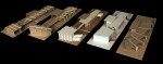
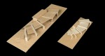
Assignment 5: The ‘Wall’-Structured House
Posted by codymblanchard under Cody Blanchard, Jordan Crawford | Tags: Assignment 5, Cody Blanchard, Jordan Crawford |Leave a Comment


We determined our spatial composition from a single construction-based concept. That concept was derived from simple conceptual sectional sketches. The sketches were refined through process with the materials, structural elements, and their logical assembly method in mind. As a result, a single thick concrete wall held together our collection of light-wood framing spaces. In assembly, temporary joists are placed into the formwork before concrete is poured. Once poured and set, the temporary formwork is removed so that the real joists can be put in place. This assembly process not only acts as foundation or the backbone of support, but influences the rest of the design for the house. From a compositional standpoint, the wall seems to hold the entire house off the ground, making the spaces ‘float’ above. In terms of spacial hierarchy, our wall defines enclosed spaces contained in more open greener spaces. Within the hierarchy, our wall provides a constant change of axis along the circulation, making the spaces more organized and dynamic in a rectangular ‘shotgun’ condition, while also revealing spaces unknown to the street. In terms of efficiency, the wall acts a rainwater harvesting system, an insulator, and a solar shading device. Finally, in terms of human interaction, the occupant or visitor is constantly interacting with the wall throughout the house in their daily activities and events.
March 3, 2010
Assignment 3/4: Automobile Construction + Wind Energy System
Posted by codymblanchard under Cody Blanchard, David Borel, Tan Vu | Tags: Cody Blanchard, David Borel, Tan Vu |Leave a Comment


The purpose of these two assignments was to explore the automobile construction system, then apply the system to the space created in Assignment Two. As a result, our group created a system that includes the construction processes of automobile manufacturing (chassis, mechanical, body, and interior), and the design process so that the design has the consumer in mind (so construction maximizes efficiency: time, material, labor, sunlight, and adaptability). We could not follow our automobile construction process exactly because the space from Assignment Two called for the incorporation of a solar updraft tower located in the center of a building. This method could only be done efficiently if the building was built after the solar updraft tower was completed, and we wanted to explore the possibility of putting our tower into a building that was already built.
Now the system consists of a combination of a cone-like solar updraft tower and a wind turbine inside a building, and a qanat, an underground water management system, all used for wind creation and harvesting. The problems came with the shape and location of the cone inside the building. If we wanted to put the tower in the center of a building, not only would we have the difficulties of excavating the shape of the tower in the building, at least two facades and the roof would have to be redone in order for the system to work. Consequently, we decided to situate the tower on the southwest corner of a building to minimize the demolition area and to maximize sun exposure.
Experimenting with various top shapes of where the wind hits the wind turbine and the overall shape of the tower, we were able to identify two problems. The first problem was to determine installation methods that assimilated some ideas from our automobile project. Essentially, the task was to merge two objects of separate conceptual components, i.e., a chassis, a mechanical system, an exterior body, and interior components. After much debate and brainstorming, we decided to use the building’s chassis (columns and beams) as the tower’s chassis. Maximizing the shape of the tower nozzle, i.e., conforming the nozzle shape to the circular turbine, caused another problem of casting more shadowscompared to an aerodynamically inefficient triangular prism tower, which can virtually have no shadows cast from the building: catch-22. After virtual sunlight exposure testing of several alternatives, we ultimately decided that we should focus on a solar updraft tower that maximizes the nozzle, but we would raise the tower by two stories to compensate for the expected casting shadows.
Even though our group did not follow our previous construction process of automobiles to the exact detail, we still accomplished the task of reinventing the original solar updraft tower through several means. We were able to combine some of the four construction concepts, e.g., the tower’s electrical system (interior) became a part of the building’s electrical system, and that electrical system is integrated into the building’s structure (chassis). We were also able to recognize the material, labor, and time inefficiencies of the original design; and through research and virtualsunlight testing of various shapes of the nozzle and tower space, we took the initiative to situate the tower on a southwest corner for maximum sun exposure, increase wind efficiency (more speed and turbine exposure) by making the nozzle a circle, and compensate for the loss of sunlight exposure (due to the shape of the nozzle) by raising the tower. Overall, our final model is a vast improvement from assignment 2, espcially in efficiency.
February 10, 2010
Assignment 2: Wind Powered Energy Production: Cody Blanchard
Posted by codymblanchard under Cody Blanchard | Tags: Assigment 2, Cody Blanchard |Leave a Comment


The main problem with wind- energy production is that the wind is so very unreliable. My system remedies that problem by using tried and true air-flow techniques to ‘create’ wind. A cone-like space that made of all glass collects sunlight and heats up. The hot air inside the space rises out of the ‘nozzle’ at the top of the space. The cone shape of the space helps to give the rising air more velocity. Then, cool air from an underground water source space rushes upward to replace the hot air, creating wind by definition. That wind turns the turbine inside the cone-like space, which powers the building that the system sits in. My system could possibly fit inside any multistory building, acting as the buildings atrium. It could also hold plants, and act as a greenhouse. It is a system that creates its own natural energy, wind, and turns it into electricity.
January 28, 2010
Sustainable Sites: Heat Island Effect, Surface Water Management
Posted by codymblanchard under Cody Blanchard, LEED Research | Tags: Cody Blanchard, Surface Water Management, Sustainable Sites: Heat Island |Leave a Comment
http://www.dec.ny.gov/lands/30344.html
http://www.concretethinker.com/technicalbrief/Cool-Communities.aspx
http://aa.usno.navy.mil/data/docs/AltAz.php
For the last link, click the Guide to Stormwater Best Management Practices in Chicago
